Crossing Detector
The Crossing Detector integration will traverse the field network topology of the open project and list out all detected connection crossings in a list with options to directly navigate to each specific crossing in the Viewport for review. As crossings usually are a costly endeavor this will assist the FieldTwin Design user to quickly review all crossings and export the data if desired.
The short video above shows the crossing module in the lower half of the screen after it is enabled on the tenant and is ready to use. The video also demonstrates the basic functionality.
Enable Integration
To enable the Crossing Detector on your tenant, please contact your FutureOn Customer Success representative. Once enabled, to start using the integration, open a FieldTwin Design project and select the Layout button on the topmost right toolbar as shown below:
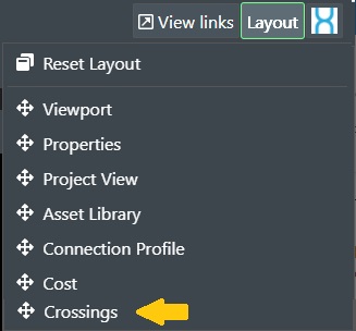
Then select the Crossing Detector entry from the list. It will then appear in FieldTwin Design and it is ready for use. Simply drag and drop the window in the desired position.
Commands
The following commands are available:
Process - Press this button to start the crossing detection process.
The network topology gets traversed, and the results are shown as follows:
Export to CSV - This will export the result list to a CSV (Comma Separated Values) file that will be saved in your Download folder.
Fit All - Press this button to make sure the results fit the display area.

Reset Layout - Press this button to go back to the original result display area.
Detection Setup Tab
The Detection Setup offers the following options:
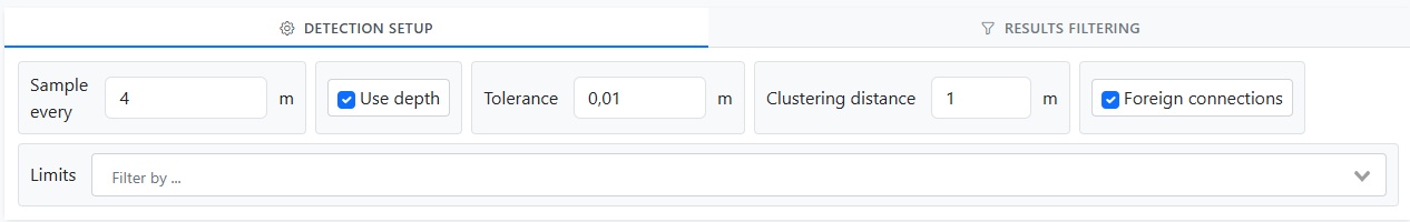
Sample every - Enter the numeric value in the unit of the project CRS (Coordinate Reference System) for sampling frequency on the connections.
Use depth - Enter the numeric value in the unit of the project CRS to define the maximum depth needed to consider the section as a crossing.
Tolerance - Enter the numeric value in the unit of the project CRS to define the maximum depth tolerance to consider the section as a crossing.
Clustering Distance - Enter the numeric value in the unit of the project CRS to define the maximum clustering distance to the consider section as a crossing.
Foreign connections - Tick the box if you want to include connection(s) from parent projects, unselect if you want to exclude foreign connection(s).
Limits - You can filter what is to be included in the detection by selecting one or more options from the drop-down list comprised of View, Selection, and Selection Only.

Results Filtering Tab
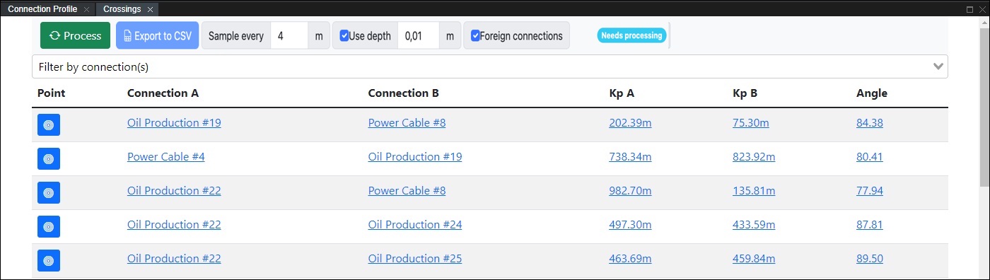
After pressing Process based on selections from the Detection Setup tab any detected crossing will be displayed and the tab focus shifts automatically to Results Filtering tab as shown below:
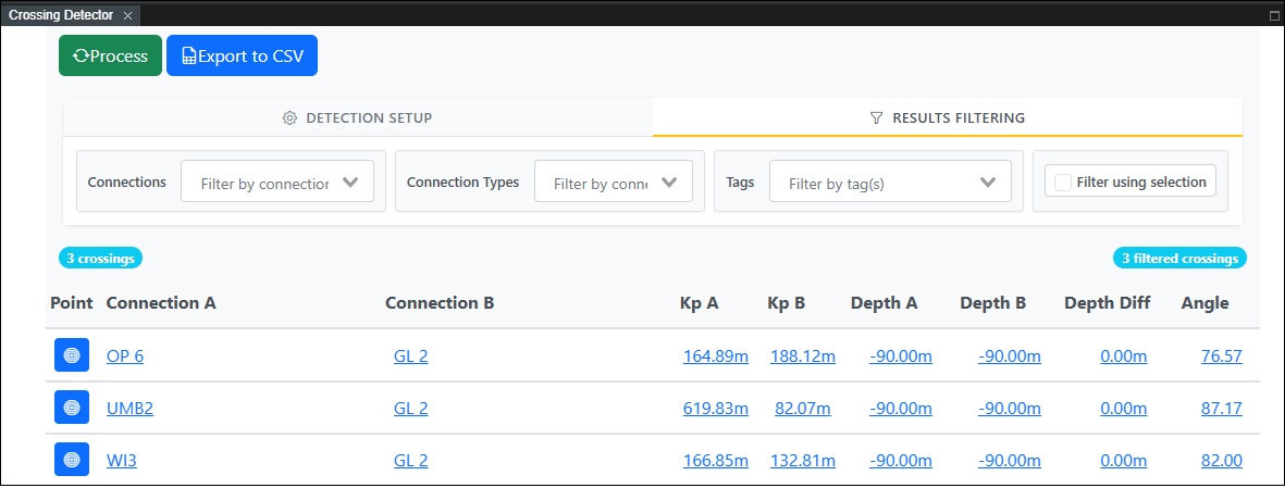
The results displayed can be further narrowed down by the following filtering options:
Filter by connection(s) - Select the connection(s) from the drop-down list you want the crossing detection to specifically include.
Filter by connection type(s) - Select the connection type(s) from the drop-down list you want the crossing detection to specifically include.
Filter by tags(s) - Select any tag(s) if defined from the drop-down list you want the crossing detection to specifically include.
Filter using selection - Will display results based on your current viewport selection.
Results List
The found crossings based on detection criteria’s and results filtering operations are shown and offer the following additional navigation commands:
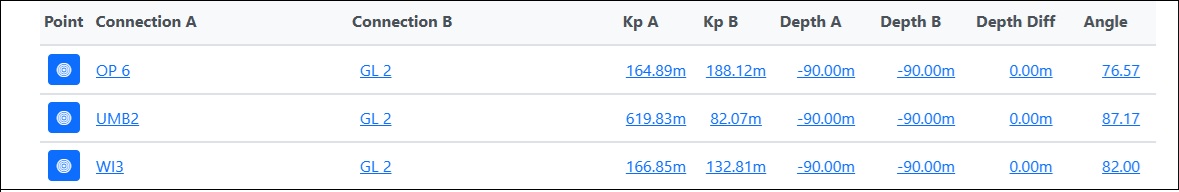
Note! - The various Result Columns can be resized and/or rearranged by drag and drop.
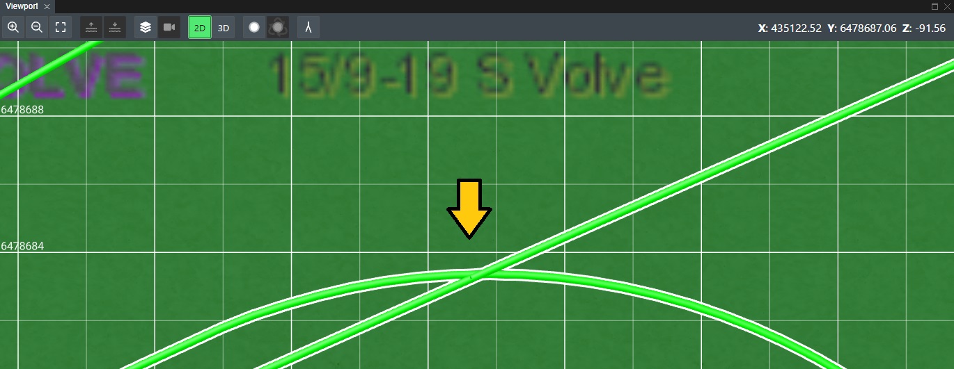
Point - Press this button to navigate to the detected crossing in the Viewport.

The Viewport will then be zoomed to the specific crossing point as shown below:
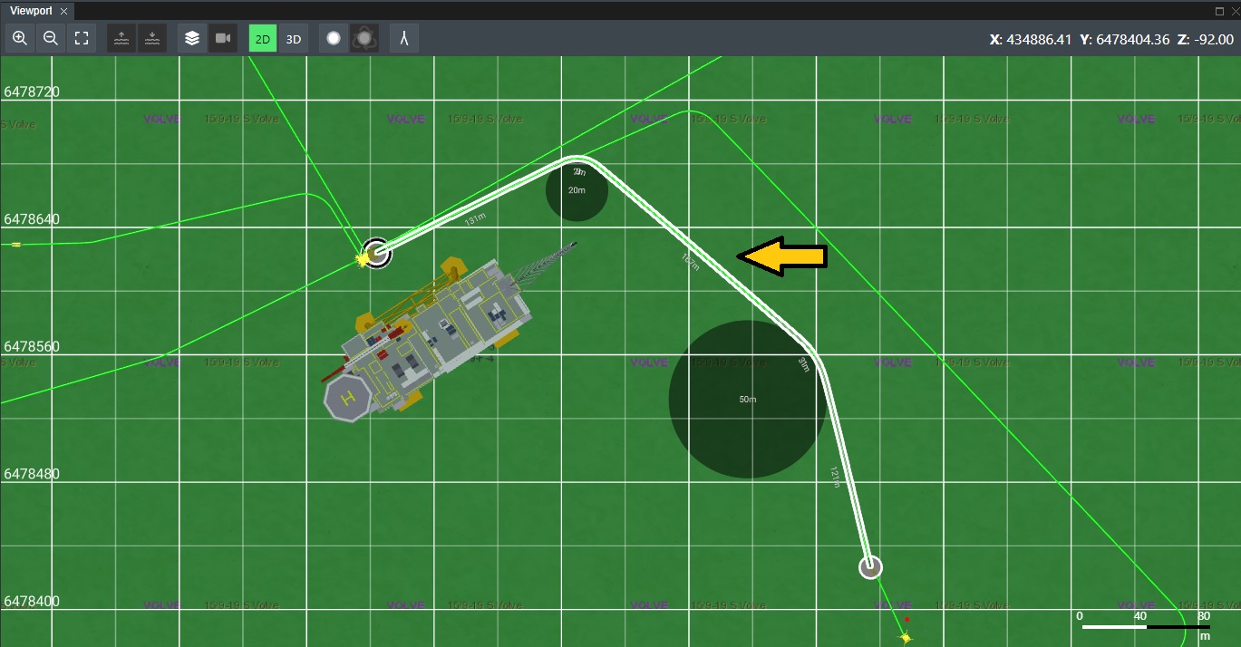
Connection A - Each entry in the Connection A column is a connection that is involved in the crossing. It is shown in blue underlined text and can be clicked on, which will then show that connection highlighted in the Viewport.
The Viewport will then reflect this as shown below:
Connection B - Each entry in the Connection B column is the other connection that is involved in the crossing. It is shown in blue underlined text and can be clicked on, which will then show that connection highlighted in the Viewport.
Kp A - This column shows the Kp value in the units of the project CRS for connection A on the intersect. Click on this to be taken to the KP A position in the Viewport.
Kp B - This column shows the Kp value in the units of the project CRS for connection B on the intersect. Click on this to be taken to the KP B position in the Viewport.

Depth A - This column shows the Depth value in the unit of the project CRS for connection B on the intersect. Click on this to be taken to the Depth A position in the Viewport.

Depth B - This column shows the Depth value in the unit of the project CRS for connection B on the intersect. Click on this to be taken to the Depth B position in the Viewport.

Depth Diff - This column shows the Depth difference in the unit of the project CRS for connections A & B on the intersect. Click on this to be taken to the Depth Diff position in the Viewport.

Angle - Displays the value of the angle in degrees for the crossing intersect. Click on this to be taken to that position in the Viewport.

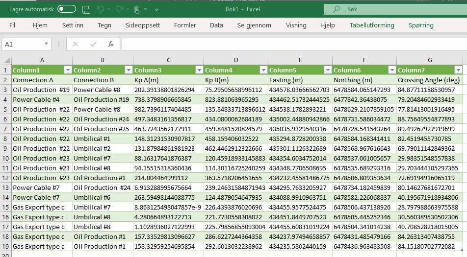
CSV Export
You can easily open the exported CSV file in MS Excel. The easiest is to go to Data and then select the From Text/CSV option. Select the exported file in your Download folder and MS Excel will place the values directly into the right columns, and the result with be like this: